Whole-Body Rehabilitation Device
Mechanical design of a collaborative rehabilitation platform
Mechanical design and analysis for a collaborative whole-body rehabilitation platform, with an undergraduate thesis focused on the knee-and-shoulder accessory and design contributions incorporated into a commercial product.
Overview
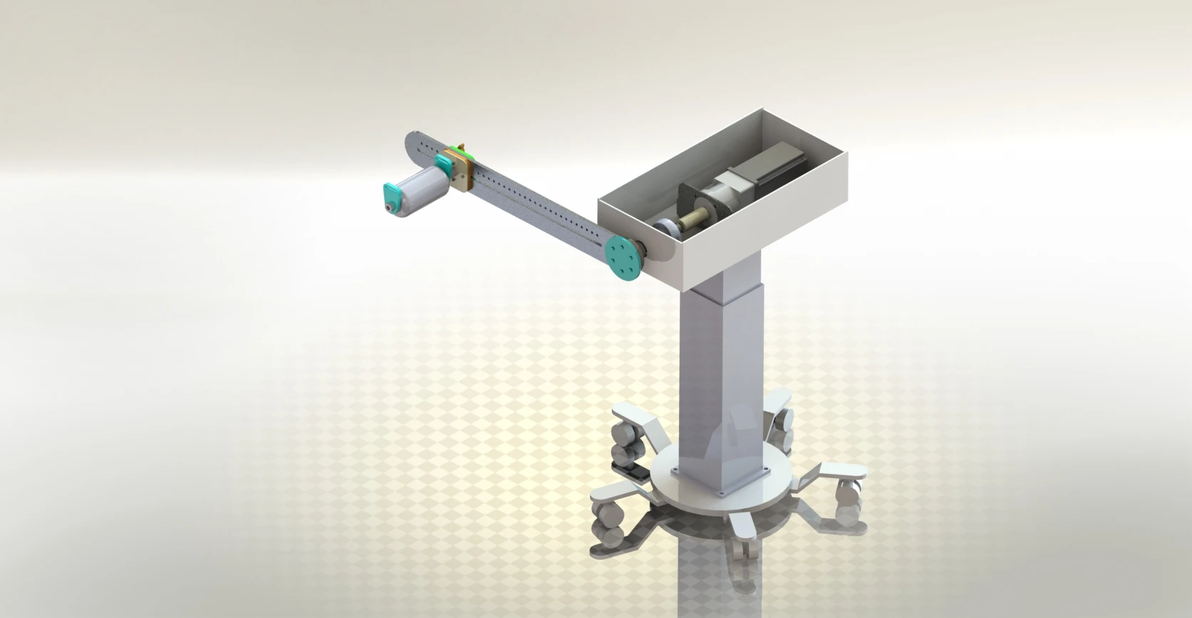
This collaborative project addressed a whole-body rehabilitation device built around a common powered platform and interchangeable accessories. Instead of designing a separate drive system for every joint, we explored how a shared mechanism could accommodate different movements through accessory changes and alignment with the intended joint. The knee-and-shoulder accessory uses a rotating arm to support a limb during continuous passive motion.
My undergraduate thesis at the University of Tehran documented that accessory and its associated mechanisms. The broader project also included a colleague’s work on another accessory and manufacturing. My design contribution was incorporated into the device manufactured and marketed by Teb Sanat Sharif / Sharif Exo as the Zeus Multi-CPM. The figures below show the thesis-stage design.
My Contribution
My work focused on mechanical design and analysis across the device, with the knee-and-shoulder accessory forming the scope of my individual thesis. I worked on the adjustable arm and limb support, power-transmission components, and the arrangement of the shared platform. The report brings together concept selection, SolidWorks models, loading assumptions, component calculations, and manufacturing drawings.
We divided the academic work between different accessories while contributing to the broader device project. My colleague primarily handled manufacturing; the physical production work should therefore be credited separately from my design contribution. The company’s commercial product represents the combined work of multiple contributors. This case study concentrates on the mechanical decisions and analysis documented in my thesis.
Design Requirements
The mechanism needed to accommodate different limb lengths and allow its rotation axis to be aligned with the joint being moved. For the knee-and-shoulder accessory, the design uses one powered rotational degree of freedom. Repositioning and configuring the mechanism allows different intended movements to be addressed individually.
The support needed to hold the limb without unnecessarily constraining its natural orientation. Length adjustment, height adjustment, accessible attachment points, and the ability to remove the limb were therefore important design considerations. Avoiding unintended loading depended on both the accessory geometry and how the device was positioned.
Anthropometric dimensions and estimated segment masses provided the initial sizing and loading inputs. These were design assumptions rather than demonstrated operating limits. Component availability also shaped the solution: the drive, bearings, couplings, and lifting mechanism needed to be compatible with parts that could be sourced and manufactured locally.
Mechanical Design
Concept selection and adjustable support
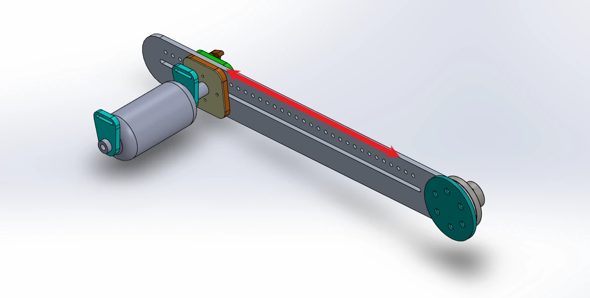
I compared alternative arm-adjustment concepts, including an aluminium-profile slider and a tube-and-clamp arrangement. The selected design uses a slotted main arm, a sliding support assembly, and discrete locking positions. This arrangement provides a defined adjustment path and addresses the risk of unwanted rotation associated with a simple clamp.
The padded support mounts on a rod connected to the slider. Its rotating cushion was intended to accommodate limb orientation while the arm moves. Phosphor-bronze bushes were included at sliding interfaces, and a locking screw locates the support along the arm. The same accessory geometry was considered for supporting the elbow during shoulder movement and the ankle during knee movement.
Drive, coupling, and platform
The power path combines a motor and gearbox, a coupling, a stepped shaft supported by two bearing units, and a splined flange connecting the accessory. I compared coupling approaches before selecting the splined connection, which separates torque transmission from the screw used to retain the flange axially.
An electric lifting column provides height adjustment, while a wheeled base allows the platform to be repositioned. These shared elements support configuration of the device around the selected accessory and movement.
CAD simulation
The animation illustrates the modeled mechanism’s motion. It is a CAD simulation from the defense presentation, rather than a demonstration of patient use or physical testing.
CAD simulation of the rehabilitation mechanism
Read transcript
A fixed CAD view shows the wheeled base, height-adjustable column, drive housing, and long accessory arm. Over approximately eight seconds, the arm rotates about the drive shaft, moving the padded limb support through an arc. The base remains stationary. This animation illustrates the modeled mechanism and does not show a patient or physical prototype testing.
Load Analysis and Component Sizing
I used anthropometric data to estimate limb dimensions and segment masses, then defined load cases for the arm and transmission components. The calculations included limb and accessory weight, bearing reactions, and additional assumed forces representing possible disturbances. SolidWorks Motion was used to investigate the drive requirement within the modeled configuration.
Shaft sizing combined bending and torsional loading with a Goodman fatigue calculation. Bearing selection was revisited after determining the critical shaft diameter, connecting the calculated geometry to an available bearing unit. Static analyses also examined the main arm, the support-rod connection, and the splined flange.
The drawings translated the CAD geometry into dimensioned parts for manufacturing. Material choices and joining methods were considered alongside sourcing: for example, a rod-and-plate connection allowed the support assembly to be bolted to the slider. Together, the calculations and drawings connected the mechanical models to component selection and manufacturing.
Manufacturing and Commercial Outcome
My mechanical-design contribution was incorporated into the rehabilitation device manufactured and marketed by Teb Sanat Sharif / Sharif Exo. My colleague primarily handled manufacturing, connecting the collaborative design work to physical production. The commercial outcome gives the project a practical context beyond its individual thesis submissions.
The company presents the current product as the Zeus Multi-CPM. That page describes the commercial device; the CAD views and analyses here document the earlier thesis-stage design. My contribution described here concerns mechanical design and analysis. The current product’s software, clinical performance, certifications, and later features are outside the scope of this case study.